
HT series industrial burner
keyword:
Category:
HT series industrial burner
The HT series industrial burner consists of three major series, including fuel burners (including light oil, heavy oil, fuel oil, and waste oil), gas burners (including natural gas, liquefied petroleum gas, blast furnace gas, producer gas, coke oven gas, and industrial exhaust gas), and oil gas mixed combustion burners, consisting of over 180 varieties. Since its inception, this series of products has gained the admiration and love of a large number of users due to its novel structure, advanced combustion mechanism, and significant energy-saving effects.
HTP fuel burner
1、 Introduction to HTP series fuel burner combustion products
The HTP series fuel burner is designed to burn light oil, heavy oil, fuel oil, and heavy oil. Its advanced design allows for the complete process of atomization, vaporization, uniform mixing with air, and complete combustion without the furnace. It emits a pure flame that is high-temperature, high-speed, smokeless, and dust-free, which is unparalleled by any other burner at home and abroad.
The HTP series oil gas mixed combustion burner can not only burn single fuel and gas, but also perform oil gas mixed combustion, which is highly popular among oil and gas users.
2、 Specifications and technical parameters of the burner
1. Specification and model of burner
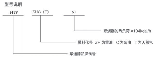
The HTP series fuel burner is composed of an oil gun, a burner assembly (including the shell and flame chamber), etc.
The HTPZHC type can burn light oil, heavy oil, crude oil, and heavy oil, with 14 conventional specifications. The HTPC model can only burn oil and has 5 conventional specifications.
2. Technical parameters of burner operating conditions
1) Fuel supply pressure in front of the oil gun
Light oil: 0.8MPa (variable range 0.5~1.5 MPa)
Heavy oil: 1.2MPa (variable range 0.8~2.4 MPa)
2) Oil supply temperature before the oil gun
Light oil: > 0 ℃
Crude oil: ≥ 70 ℃
Fuel oil: 60~90 ℃
Heavy oil: ≥ 110 ℃
3) Fuel viscosity
≤4.5°E
4) Combustion air pressure entering the burner
Light oil: ≥ 3kPa
Heavy oil: ≥ 4kPa
5) Temperature of combustion air entering the burner
-10℃ ~ 400℃
6) Adjustment range of burner thermal load
50% rated load to 130% rated load
7) Combustion products
CO ≤ 0.1%, dust content ≤ 70mg/Nm3
Note: This parameter is for theoretical reference and subject to change without prior notice. The actual product shall prevail.
3、 Selection of burners
1. Conventional burner selection
The types of conventional burners include:
1) HTPZHC type (heavy oil type)
2) HTPC type (diesel type)
2. Abnormal burner
1) Giant or micro burners: Those with an hourly fuel consumption exceeding 1600 kilograms or less than 8 kilograms are referred to as giant or micro burners, and are not part of the standard series and require special design and supply.
2) The long tube burner that extends into the furnace, with the high-temperature section on the rotary kiln several meters away from the furnace head, usually needs to be extended into the furnace. The burner shell is made of a interlayer and cooled by water. This type of burner has been used in hundreds of rotary kilns and calciners for many years, and the effect is very good.
3) Low temperature burner: Some materials have a very low heating temperature, such as drying laundry detergent. This type of burner itself adds secondary air and controls the flame temperature between 200 ° C and 500 ° C.
4) Oil and Gas Triple Use Burner: After installing a gas package on the HTPZHC burner, natural gas or coal gas can be introduced for mixed combustion of oil and gas, or single combustion of oil and gas, which is favored by users who need to use both oil and gas at the same time.
5) A burner with a boiler bellows plate is installed. Some boilers have bellows plates. In order to simplify installation, our company has designed a burner with a bellows plate, which can be used for single burning of oil, single burning of gas, and mixed burning of oil and gas.
When placing an order, users only need to indicate the thickness of the bellows.
4、 Supporting equipment
1. Fuel supply system
1) The oil circuit and supporting devices are self-made by the user.
2) The oil pipe should be made of chicken free steel pipe with a pressure resistance of 3MPa, and each connection should be sealed. The pipe diameter should be greater than φ 14。 Application of the oil pipe connected to the pipe joint of the oil gun φ 12 metal hoses or copper pipes. There should be steam insulation on the heavy oil pipeline (the steam temperature should not be lower than 140 ℃). The oil pipeline should be equipped with a filter screen (depending on the size of the burner and the type of oil used, the filter screen should be selected between 60 and 100 #), preferably in parallel with two sets for alternate cleaning.
3) The oil pressure gauge should be installed between the fuel injection gun and the oil valve, and the oil valve should be able to be fine tuned.
4) The oil supply pump can generally be gear pump or vortex rod pump. High temperature resistant oil pump should be used for transporting heavy oil, and ordinary gear pump can be used for transporting light oil.
2. Heavy oil heating device
Heavy oil heating generally adopts the following three methods:
1) Heating with high-temperature steam casing or tracing pipe;
2) Heating with a specialized steam heating package;
3) Heat with an electric heater.
3. Automatic thruster
Used for automatic advance and retreat of oil guns and ignition guns. It can be electric or pneumatic; It can be used alone or in conjunction with the system.
4. High-energy igniter
Used for automatic ignition of fuel and gas burners. It can be used alone or in conjunction with the system.
5. Fuel solenoid valve
Used for opening and closing fuel and gas pipelines. It can be used alone or in conjunction with the system.
6. Fuel electric regulating valve
Used in conjunction with fully automatic burners, it can meet the temperature requirements of the furnace, receive a 4-20mA current control signal, and achieve temperature control by automatically adjusting the fuel volume.
7. Air electric control valve
Used in conjunction with fully automatic burners, it can receive a 4-20/A current control signal according to the furnace temperature needs, and synchronize with the fuel electric adjustment switch to automatically adjust the air volume to meet the combustion requirements.
8. Flame monitor
Used for monitoring the combustion process. When the furnace accidentally shuts down, a signal, sound and light alarm can be issued, and the fuel solenoid valve can be cut off to protect the equipment and prevent accidents. Often used in conjunction with solenoid valves and alarms.
9. Automatic combustion control system
The automatic combustion control system is composed of an air oil ratio regulator, an automatic thruster, a high-energy igniter, a flame monitor, an electromagnetic valve, and an electrical control cabinet. It can achieve automatic fuel supply and ignition, operation monitoring and adjustment, proportional adjustment of fuel/air volume based on temperature (or pressure), and shutdown alarm protection for the burner. Our company can combine various functions according to customer needs to meet requirements.
5、 Installation and process flow of burner
1. Introduction diagram of the installation and system process flow of the burner.
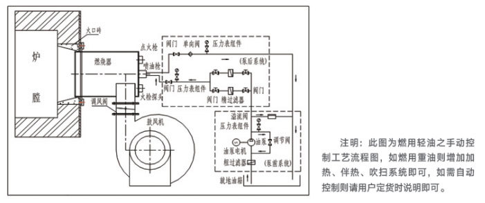
2. Installation instructions for the burner:
a. The length of the furnace wall fire brick should not be longer than 300mm, and the fire mouth should have a 40 ° cone angle. There should be a 5mm gap on each side between the burner shell and the minimum diameter of the fire mouth, and it should extend into 30-60mm. The burner and the fire mouth should be concentric. After installation, spot weld the movable flange onto the burner shell and secure it with a pressure plate.
b. The diameter of the oil pipe should be suitable for the flow rate of the fuel, and there should be no folding or flattening.
c. Light oil process pipelines and heavy oil pipelines should be equipped with light oil ignition, steam sweeping, heating system, and steam insulation pipelines (the temperature of heavy oil should not exceed 90 ° C before the oil pump, and it should be reheated after the oil pump), and insulation materials should be outsourced.
d. The air inlet can be oriented in any direction, and the height and angle of the fire opening from the furnace are selected by the user.
e. The cross-sectional area of the air duct should be about 40% larger than the area of the burner's air inlet hopper.
f. Drill on the intake pipe after the air valve φ 8 holes as an interface for measuring wind pressure.
g. Inspection work before the first ignition: Check the installation of the burner and supporting parts for completeness, check the safety and smoothness of the oil circuit, circuit, and air circuit, and then remove the oil pipeline from the oil gun. Open the oil regulator, drain the oil into the barrel for 5-10 minutes, and then reconnect the oil pipeline to the oil gun (this purpose is to remove impurities in the oil pipeline).
h. Preparation before each ignition: Remove accumulated slag and debris from the furnace, open the air door, and blow the furnace for 5-10 minutes. Check the air and oil circuits, and adjust the air pressure and oil pressure to the appropriate state. (If heavy oil is used, the steam valve for heating the heavy oil should be opened for about three minutes. When the accumulated water in the pipe is completely discharged and the steam starts to emit, the valve should be closed. Then, the sweeping steam valve and the hand wheel adjustment on the oil nozzle should be opened to spray steam into the burner and furnace along the uninsulated oil path and nozzle. The oil path and nozzle should be preheated, and the steam can be turned off after about 10 minutes when the surface of the nozzle body is hot.)
6、 Fuel supply system
1. Light oil supply system.
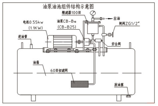
a. This fuel tank is only suitable for diesel and not for heavy oil. It consists of the fuel tank shell, coarse filter (60 mesh copper wire mesh), fine filter (100 mesh copper wire mesh), CB-B10 oil pump, electric motor (0.55kw1400 rpm), 0-2.5MPa pressure gauge, safety valve, gate valve, etc.
b. This fuel tank can be placed in a safe place near the burner. The oil pipe should not be too thin or too long, and should be placed smoothly. It is allowed to be fixed without foundation screws.
c. Open the protective cover and add approximately 200 liters of diesel.
d. Connect the power supply, start the oil pump motor, and ensure that its direction of rotation is consistent with the direction indicated on the oil pump indicator. If the direction of rotation is incorrect, the oil pump will not pump oil, and the operation should be flexible and noiseless. The motor and oil pump casing temperature should be normal for 1-2 minutes before long-term operation.
e. Close the gate valve, and when the pressure gauge reaches the maximum value of 2MPa, only the return oil pipe of the safety valve returns oil, and the pressure gauge pointer should not jump. When adjusting the oil pressure, turning the gate valve clockwise will increase the oil pressure, and vice versa will decrease the oil pressure. The oil pressure can be adjusted arbitrarily below 1.5MPa and can remain stable. The safety net has been adjusted before leaving the factory. Users should not easily adjust it to avoid damaging the oil pressure gauge due to high oil pressure.
2. Heavy oil supply system
matters needing attention:
a. Setting of fuel pressure: Adjust the pressure for burning light oil between 0.5~1.2Mpa; The pressure adjustment for burning heavy oil is suitable at 0.8~1.8Mpa.
b. During use, the fuel tank should be covered with a protective cover to prevent debris, dust, and water from entering the fuel.
c. The oil storage in the oil tank should ensure that the coarse filter does not expose the oil surface to prevent air from being sucked into the oil circuit. Sediments and accumulated water at the bottom of the oil tank should be regularly removed, and the coarse filter and fine filter must also be regularly removed for cleaning to ensure smooth oil circuit. Install the pressure gauge and pressure gauge gasket on the fine filter, install the oil outlet pipe, and ensure that there is no oil leakage at each connection.
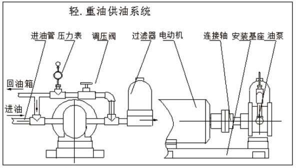
3. Light and heavy oil supply system
a. This oil supply system can be used for both light oil pressurized oil supply and heavy oil pressurized oil supply.
b. The oil supply system can be installed on the pipeline according to on-site needs or used on the fuel tank according to needs.
c. When installing the oil supply system, it must be noted that if the fuel consumption of the burner used is below 400L/h, the return oil must be returned to the oil supply box, otherwise the return oil on the oil pump can be directly returned to the front of the oil pump.
4. Heavy oil electric heater
1) The structure of the heavy oil electric heater consists of a shell, two U-shaped electric heating tubes (220V, 2KW), a thermometer sleeve, an oil inlet joint, an oil outlet joint, and a power cord junction box.
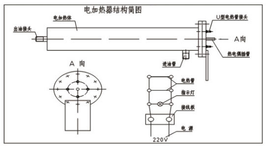
2) When transporting to the oil inlet joint of the burner, if the temperature of the heavy oil reaches 100 ° C, this electric heater can be installed in the oil pipeline within about 1 meter near the burner. Pay attention to connecting the power supply only after the heavy oil enters the electric heater. When stopping the oil supply, the power supply of the electric heater should be cut off first to prevent burning the electric heater.
3) Two 220V and 2KW electric heating pipes, used in parallel, with a total power of 4KW. The general fuel quantity is: 60~220Kg/h, and two 4KW electric heaters are selected.
4) Although this electric heater has undergone a 2.4MPa pressure test, the working oil pressure should not exceed 2MPa, and oil leakage is not allowed at the joints of the electric heater and oil pipes.
5) This electric heater is equipped with a thermometer sleeve, which is inserted into the measuring head of a 300mm long, 200 ° C automatic temperature sensor (provided by the user) for automatic measurement and control of oil temperature.
6) When installing an electric heater, users can add an insulation layer outside the shell to improve thermal efficiency.
7) The electric heating tubes R1 and R2 of this burner are connected in parallel with the indicator light, and the power is connected to the knife switch through a 2.5mm2 power cord. When the indicator light is on, it indicates that the circuit is connected, but whether the electric heating tubes R1 and R2 are working properly can only be determined by measuring whether the oil temperature has increased.
Note: If a higher power electric heater is required, our company can design and manufacture it separately according to specific requirements.
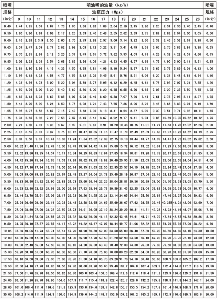
5. Nozzle flow parameter table
Contact Us
Address: No. 51 Jinma Road, Yuhua District, Shijiazhuang City, Hebei Province, West America Wuzhou MOCO1403
Related products
Get product quotes for free
Our staff will contact you within 24 hours (working days). If you need any other services, please feel free to call the service hotline:+86-0311-87777707


